Dear all,
***
Find a name/title for your project!
+
When you post (you all have to post this week-end), in the bottom right line called Label, write your name and the name of your project.
***
Reminder of the general requirements for the review:
_ ANALYSIS & REFERENCES
The essentials of your specific analysis. Relate it to your proposal, either chronologically, or in your own way, according to what we agreed upon during tutorials today.
The references (other projects by architects or artists) you used during the development of your project:
what you extracted from them + how you transformed it in order to serve your idea.
_ TECHNICAL DRAWINGS -
They do not fit on A2 paper!
All should include the context: ground, street, walkways, buildings, cars, people, vegetation ...)
All have to be labelled with TITLE (title of your project), NAME (the name of the person who executed the drawing, hopefully you!), VIEW (name of the projection: site plan, elevation, section AA', section BB' etc.) and the SCALE.
You can specify the dimensions, the elements, the materials used etc.
You are warmly invited to experiment with those drawings, to make them specific to your project, but you need to understand the basic conventions behind each one of them.
- site plan at scale 1/100 (showing the whole context of the bridge in its site, you have to indicate the north direction) ***NEW***
- plan at scale 1/50 (this plan, called floor plan, is actually a horizontal section cut through the bridge at one metre above floor level / the plan has to show where the sections are cut with a broken line and triangles + letters at both extremities of the line to indicate from which side the section is drawn - example)
- elevation at scale 1/50 (flat representation of one "façade" - example)
- axonometric projection (exploded or not, at scale 1/50 unless otherwise specified during tutorial)
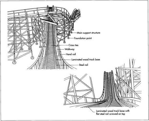
- longitudinal section at scale 1/25 (showing construction details)
- cross section at scale 1/25 (showing construction details)
About the sections...
Everything cut by the section plane is shown as a bold line (possibly with a solid fill to show objects that are cut through) and anything seen beyond is shown in a thinner line (you can establish a gradual decrease of the thickness in relation to the distance).
It seems that many of you have never done architectural technical drawings before - here is a basic wikipedia description. Please read and observe carefully.
_ DESIGN PROCESS
sketches / study models / researches / experimentations / diagrams / etc.
Present your design process, whether about form finding, technical experiments, ideas, intuitions, tests (even unsuccessful) etc.
You need to show clearly the the different stages of your design process.
_ FINAL IMAGES AND MODELS
- Several renderings of you final proposal (according to tutorials discussions).
- The final model at scale 1/50, showing :
the context according to what is relevant to your project,
an idea (as developed as possible) of the structural system supporting your bridge,
the materiality (material used in reality) + overall appearance of your design,
- The 1/500 model to be placed and photographed in the site model.
Plus detail / technical models if specified individually.
Those are the minimum requirements.
If you think your project would better understood by showing a video, an animation, another type of drawing, a full scale model etc., we will be more than happy to see that!
Post work and questions.
Good luck to all!


